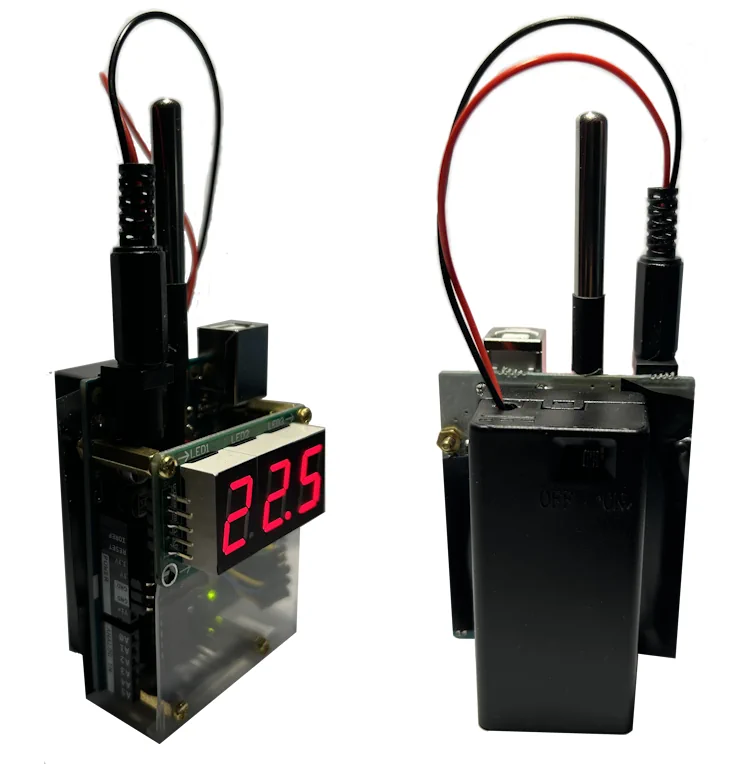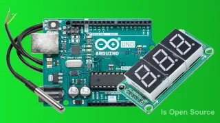
Φτιάχνουμε ένα θερμόμετρο με Arduino, αισθητήρα θερμοκρασίας DS18B20, και ένα module οθόνης 3 ψηφίων
Είχα ένα περισσευούμενο Arduino UNO και έναν αισθητήρα θερμοκρασίας DS18B20 και αποφάσισα να φτιάξω ένα θερμόμετρο ακριβείας (κάτι που ήθελα να κάνω εδώ και πολύ καιρό). Μιας και ήθελα να είναι φορητό συμπεριέλαβα και μία μπαταρία 9V για να τροφοδοτήσω το Arduino. Για να εμφανίσω τη θερμοκρασία χρησιμοποίησα ένα module 7-segment 3 ψηφίων το οποίο διαθέτει ενσωματωμένους 3 74HC595 shift registers και μπορείς να το χειριστείς μόνο με 3 αγωγούς. Σας συστίνω να χρησιμοποιήσετε το module και όχι 3 αυτόνομους shift registers για να γλυτώσετε τις κολήσεις (θα πρέπει να γίνουν πάρα πολλές συνδέσεις). Χρησιμοποιώ 1 δεκαδικό ψηφίο για την εμφάνιση της θερμοκρασίας σε βαθμούς Κελσίου εκτός για θερμοκρασίες κάτω των -9.9 βαθμών (γιατί θα χρειαζόμουν ακόμα ένα ψηφίο). Συνεπώς η οθόνη εμφανίζει θερμοκρασίες από -99 έως -10, κατόπιν από -9.9 έως 0.0 και τέλος, έως 99.0. Όσον αφορά στην εμφάνιση ήθελα να μοιάζει λίγο "άγριο" και "χύμα", και κατέληξα σε ένα στυλ γουόκι-τόκι (κάποιος θα έλεγε ότι μοιάζει με βόμβα). Προσωπικά μου αρέσει πολύ.
List of materials
Some of the materials listed below are optional and the thermometer can work without them. However, if for example, you want to make it portable you will need to power it with a battery. If you want to make it look like mine then buy all of the materials listed. I provide links to materials from GRobotronics web site. You will find them cheaper elsewhere however I use GRobotronics as I found all materials listed there and it is a store I like and trust to shop.
- Arduino UNO (or any Arduino variation)
- Temperature Sensor DS18B20 (Waterproof or IC)
- 3 digit 7-segment display module
- 4.7K resistor
- 9V battery (optional)
- 9V battery Holder with switch (optional)
- Dc Power Plug 5.5 x 2.1mm (optional)
- Pin header male right angle
- Standoffs (15mm height), bolts and nuts (link to a kit)
- Transparent plastic cover (optional, cut a small piece from anything)
- Cables, heat shrink tubs, and silicone glue stick (optional)
Preparing the hardware
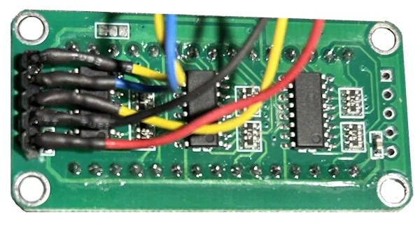
Solder 5 pins (male right angle) at the bottom of the 7-segment display module (at the P1 side) facing inside the module. These pins are labeled VCC, GND, SDI, SCLK and LOAD on the module. Solder 5 cables to each of these pins (7-8cm long, make them longer and you cut them later). Isolate these pins with heat shrink tubs (optional).
The waterproof version of the DS18B20 temperature sensor comes with a long wire. Cut this wire leaving only a few centimeters (7-8cm) of it and then glue the sensor on top of Arduino UNO. Be careful not to heat Arduino too much with the heat gun.
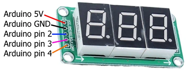
Insert a 3-pins header (male, right angle facing inside) in Arduino pins 5V, GND and GND. Insert a 6-pins header in Arduino pins 2-7. Make the following soldering.
- VCC display module → Arduino 5V
- GND display module → Arduino GND
- SDI display module → Arduino pin 2
- SCLK display module → Arduino pin 3
- LOAD display module → Arduino pin 4
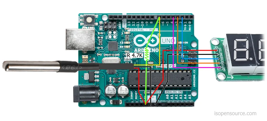
- RED cable DS18B20 sensor → Arduino 5V
- BLACK cable DS18B20 sensor → Arduino GND
- YELLOW cable DS18B20 sensor → Arduino pin 7
Put a 4.7K resistor between Arduino pins 5V and pin 7. This provides stability to the thermometer readings. Personally I have put the resistor inside a heat shrink tube for isolation (colored green in picture).
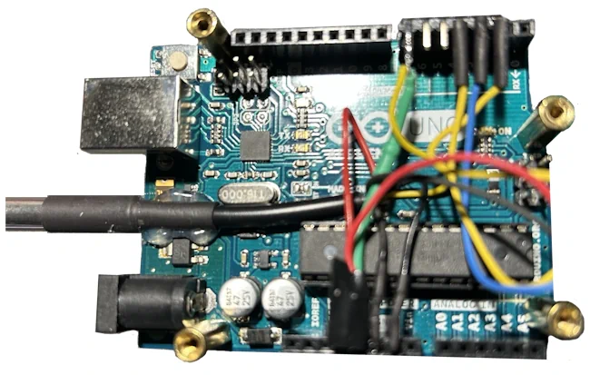
Put 4 x 15mm standoffs in Arduino holes as shown in the picture. Screw the display module on top 2 standoffs (note that the the module is about 1mm smaller so make the standoffs a little loose and the screw will fit fine. Cut a rectangular piece of transparent plastic, open 2 holes on it and screw it on the bottom standoffs on Arduino. This serves 2 purposes: a. Makes easier to hold the Arduino. b. Protects Arduino from short-circuits when touching the pins below.
Place the 9V battery inside the battery holder and solder the DC power plug to the battery cables. Glue the battery back with the heat gun in the back of Arduino. You can also put same tape on the back to protect the pins.
You can switch Arduino ON and OFF from the battery holder switch at the back.
The Arduino project
It's now time to code Arduino. Copy-paste the code below and send it to the Arduino. If you haven't library ShiftRegister74HC595 installed install it via the library manager of Arduino IDE. The begin function is just a highlight when Arduino starts, you can remove it if you like. Contact me in case you have questions.
/*
ARDUINO UNO, 7 segments 3 digits display module with 74HC595,  DS18B20 waterproof temperature sensor
I. SANNOS 11.12.2024
DATA PIN: 2 (SDI)
CLOCK: 3 (SCLK)
LATCH: 4 (LOAD)
Temp sensor DS18B20: Arduino pin 7
*/

#include <OneWire.h>
#include <DallasTemperature.h>
#include <ShiftRegister74HC595.h>
#define ONE_WIRE_BUS 7
OneWire oneWire(ONE_WIRE_BUS);
DallasTemperature sensors(&oneWire);
// parameters: <number of shift registers> (data pin, clock pin, latch pin)
ShiftRegister74HC595<3> sr(2, 3, 4);
float temp = 0.0;
int value,digit1,digit2,digit3,digit4;
uint8_t numberB[] = {
  B11000000, //0
  B11111001, //1
  B10100100, //2
  B10110000, //3
  B10011001, //4
  B10010010, //5
  B10000011, //6
  B11111000, //7
  B10000000, //8
  B10011000 //9
};
uint8_t symbolsB[] = {
  B01111111,//.
  B10111111,//-
  B11111111,//empty/off
};

void setup() {
  begin();
}


void begin() {
  sensors.begin();// Start up the library
  sr.setAllHigh();
  delay(50);
  int pinx = 0;
  for (int i = 0; i < 3; i++) {//set pins 0-5 to ON (LOW)
    for (int q = 0; q < 6; q++) {
      pinx = (i * 8) + q;
      sr.set(pinx, LOW);
      delay(50);
    }
  }

  sr.set(6, LOW);//dash
  delay(50);
  sr.set(14, LOW);//dash
  delay(50);
  sr.set(22, LOW);//dash
  delay(50);
  sr.set(7, LOW);//dot
  delay(50);
  sr.set(15, LOW);//dot
  delay(50);
  sr.set(23, LOW);//dot
  delay(50);
  //now, reverse (switch everything off)
  sr.set(23, HIGH);//dot
  delay(50);
  sr.set(15, HIGH);//dot
  delay(50);
  sr.set(7, HIGH);//dot
  delay(50);
  sr.set(22, HIGH);//dash
  delay(50);
  sr.set(14, HIGH);//dash
  delay(50);
  sr.set(6, HIGH);//dash
  delay(50);

  for (int i = 2; i >= 0; i--) {//set pins 0-5 to OFF (HIGH)
    for (int q = 5; q >= 0; q--) {
      pinx = (i * 8) + q;
      sr.set(pinx, HIGH);
      delay(50);
    }
  }
  sr.setAllHigh();
  delay(500);
}


void displayTemperature() {
  int t = temp * 10;
  if (t >= 0) {
    digit1 = t % 10;
    digit2 = (t / 10) % 10;
    digit3 = (t / 100) % 10;
    if (digit3 == 0) {
      uint8_t numberToPrint[]= {symbolsB[2],numberB[digit2],numberB[digit1]};
      sr.setAll(numberToPrint);
    } else {
      uint8_t numberToPrint[]= {numberB[digit3],numberB[digit2],numberB[digit1]};
      sr.setAll(numberToPrint);
    }
    sr.set(15, LOW);//2nd digit dot
  } else {
    t = abs(t);
    if (t > 99) {
      digit1 = t % 10;
      digit2 = (t / 10) % 10;
      digit3 = (t / 100) % 10;
      uint8_t numberToPrint[]= {symbolsB[1],numberB[digit3],numberB[digit2]};
      sr.setAll(numberToPrint);
      sr.set(15, HIGH);//2nd digit remove dot
    } else {
      digit1 = t % 10;
      digit2 = (t / 10) % 10;
      digit3 = (t / 100) % 10;
      uint8_t numberToPrint[]= {symbolsB[1],numberB[digit2],numberB[digit1]};
      sr.setAll(numberToPrint);
      sr.set(15, LOW);//2nd digit dot
    }
  }
}


void loop() {
  sensors.requestTemperatures();
  temp = sensors.getTempCByIndex(0);
  if (temp > 99.0) { temp = 99.0; }
  if (temp < -99.0) { temp = -99.0; }
  displayTemperature();
  delay(1000);
}
Διαβάστε επίσης
- Το καλάθι είναι άδειο
Εργασίες
Ολοκληρωμένα έργα
IOS Rentals v3.8
Paypal checkout, διαγνωστικός έλεγχος και άλλα29 Νοεμβρίου 2025Open Shop 4.0, 4.1, 4.2
Removal of inline events, Paypal Checkout, dialog messages, myPOS19 Νοεμβρίου 2025IOS Rentals v3.7
Διαχείριση ζημιών οχημάτων, υποστήριξη Ψηφιακού Πελατολογίου της ΑΑΔΕ28 Ιουνίου 2025IOS Rentals v3.6
Εξαγωγή/Εισαγωγή δεδομένων, επιλογές κράτησης, συνολική εικόνα και NBG.16 Απριλίου 2025IOS Hotels 3.5
Κριτικές, συνεργάτες, IOS Sync, Συνολική εικόνα29 Μαρτίου 2025Open Shop 3.9
Βελτιώσεις στις μεθόδους αποστολής και πληρωμής καθώς και στη διαχείριση παραγγελιών.28 Φεβρουαρίου 2025Plugin κρατήσεων συνεργάτη
Plugins for Elxis and wordpress to display IOS Rentals affiliate reservations10 Ιανουαρίου 2025IOS Rentals v3.5
Βελτιωμένες λειτουργίες συνεργατών και IOS Sync10 Ιανουαρίου 2025IOS Rentals v3.4
Συγχρονισμός κρατήσεων με τρίτους (IOS Sync)24 Νοεμβρίου 2024Open Form Manager
A free open source component for managing forms20 Σεπτεμβρίου 2024


